

What is SolidCraft?
SolidCraft is an open-source parametric 3D CAD application written in Rust, with desktop and browser interfaces alongside CLI and MCP automation. You sketch geometry, add dimensions and constraints, then build solids through an editable feature timeline. Changing a parameter can rebuild the dependent model.
Sketch constraints, construction references, body operations and import/export behavior determine whether a design can support later changes. Inspect the feature history and verify the exports needed by your downstream tools; a rendered model alone cannot establish that workflow.
The project describes itself as early but usable for simple parts and publishes reference models with geometry checks. Its documentation and issues track the supported boundaries and known bugs. Those checks cover a defined test corpus, rather than establishing complete equivalence with an established commercial CAD system.
The checked release is SolidCraft 0.16.2, published October 19, 2026, whose release note fixes orbit behavior around a selected point in perspective views. Apache License 2.0 covers the main repository. This profile uses official source and documentation, without an independent geometry benchmark or installation test.
SolidCraft screenshots
Explore the interface. Open a screenshot to view it at full size.
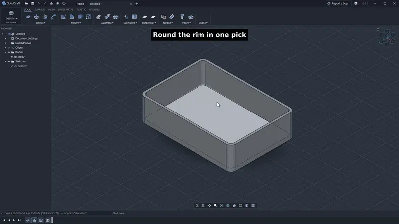
Still from the official SolidCraft 0.8 demonstration, retained as a workflow illustration; not a screenshot of an iThub test of version 0.16.2.
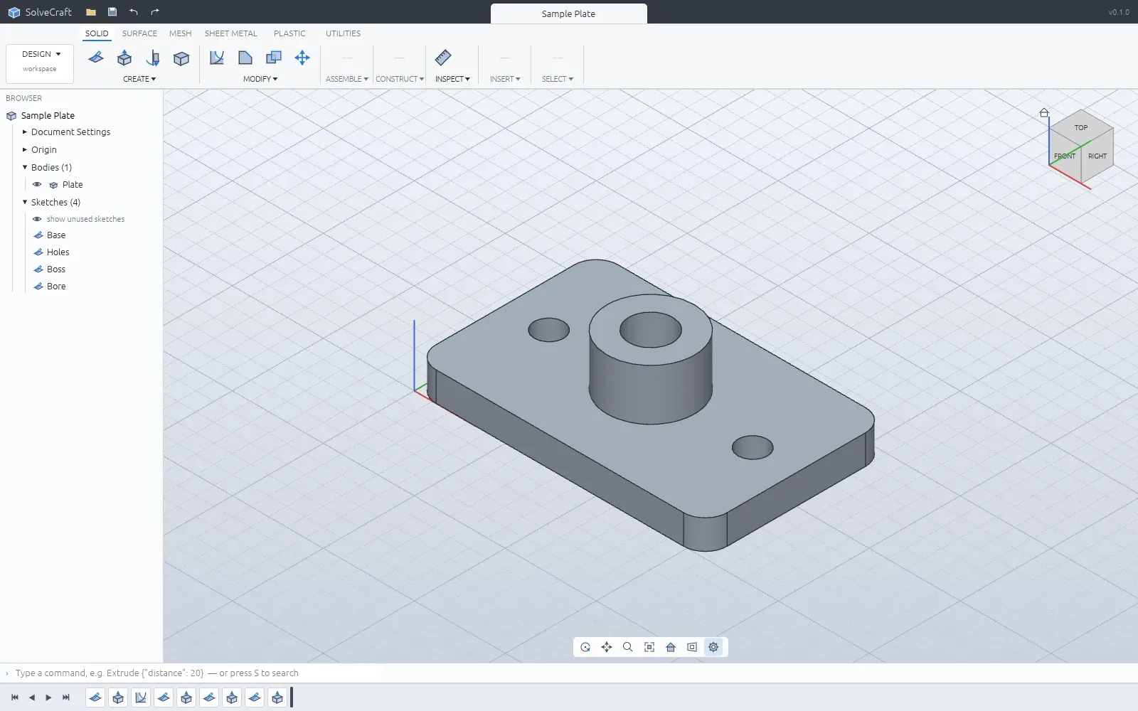
Official project model example, not an independent dimensional or manufacturing qualification.
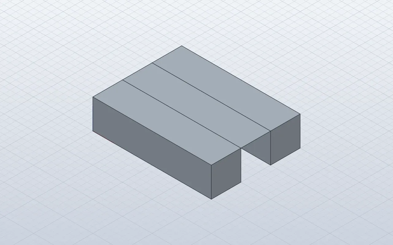
Official project geometry example; specific operation coverage must be checked in the documentation.
Source: official SolidCraft project page.
Key capabilities
- Constrained parametric sketches Create supported lines, arcs, circles and other sketch entities on appropriate planes or faces. Dimensions and constraints express the intended relationships. Inspect remaining freedom and rejected constraints while editing. A sketch that looks correct at one size may still need additional design constraints before parameters can change reliably.
- An editable feature timeline The documented feature set includes operations such as extrude, revolve, sweep, loft, fillet, shell and patterns. Supported features can be edited or reordered within their constraints. The source geometry and references matter when a later edit changes topology. Check the actual rebuild result after changing a controlling dimension.
- Parameters and configurations Unit-aware expressions connect dimensions and model choices. Configurations can adjust supported parameters, feature suppression and appearance. Keep the intended units explicit when exchanging values with another process. Test the smallest and largest variants you need, rather than validating only the original example.
- Assemblies and engineering workflows The project documents nested components, occurrences, joints, motion-related work and mass properties. Sheet-metal and plastic-part features address additional modeling tasks. Coverage is specific to supported geometry and operations. Validate the exact assembly or manufacturing workflow before relying on an advertised feature name.
- Design files and exchange formats The .solidcraft format retains the design, with JSON also supported in documented paths. Exchange formats include supported STEP, IGES, mesh and manufacturing outputs. Imported mesh bodies do not automatically recover the original parametric feature history. Use the file guide to check the appropriate route.
- Windows, macOS, Linux and browser access Official releases provide desktop packages, and the website offers a browser application. Package availability and platform-specific operations should be checked separately. The project states that downloads are not yet signed. Browser execution has its own file-access and host limitations, rather than inheriting arbitrary desktop access.
- Command-line and MCP automation The headless CLI can run command scripts, inspect geometry, export files and render supported snapshots. Its MCP mode lets an agent interact through a defined tool interface. Give the agent bounded modeling tasks and inspect the resulting design and measurements. A plausible preview does not prove a part meets its specification.
- A browser command API The documented window.solidcraft API exposes command discovery, execution and inspection in the active browser tab. It shares the design's command handling and undo history. The browser API documentation explicitly distinguishes this interface from WebMCP registration or a network listener.
Where SolidCraft fits
Building a simple mechanical part
Start with a bracket, enclosure or plate whose dimensions you can verify independently. Define the sketch constraints before adding downstream features. Change a controlling dimension, inspect the rebuilt solid and check its measurements. Export the format required by your next process and reopen that exact file in the receiving tool.
Creating a family of variants
Represent meaningful dimensions with parameters and use supported configuration rules for the variants. Test boundary values as well as the default model. Look for failed references, impossible dimensions and self-intersections after a rebuild. Preserve the native design so a later correction does not depend on reverse-engineering a mesh export.
Automating CAD operations with an agent
Use the documented MCP or command interface to create and inspect a bounded model. Ask for explicit units and dimensions, then compare the resulting measurements with the specification. Review the saved feature timeline and export. Agent access can automate operations, but the engineer still owns the fit and manufacturing decisions.
Working with existing geometry
Choose an import route that matches the actual file type and required editing. A solid exchange file and a triangle mesh carry different information. Inspect units, assemblies and body structure after import. The presence of a model in the viewport does not establish that its original constraints or editable feature history survived.
Evaluating a Rust CAD implementation
Read the Rust workspace and architecture documentation when studying the implementation. The CLI and browser command API offer concrete entry points for experiments. Keep test models and measured expectations alongside the commands that created them. Use the project's published limitations to bound the exercise before extending it to production geometry.
Reviews of SolidCraft
Be the first to share your experience with SolidCraft.
Write a review
Loading review form…
