

What is FreeCAD?
FreeCAD is a free and open-source parametric 3D modeler for designing real-world objects of any size, from small mechanical parts to buildings. Every object in a FreeCAD document is parametric: its shape is driven by properties such as dimensions, text values or other objects, and changes are recalculated on demand with a recorded modeling history. The project describes three main fields of use, product design, mechanical engineering and architecture, and its audience as hobbyists, programmers, experienced CAD users, students and teachers. It runs on Windows, macOS and Linux and does not require an account, a subscription or a sign-up.
FreeCAD is developed by a volunteer community and supported by The FreeCAD project association (FPA), a Belgian non-profit (AISBL) that collects donations and sponsorships, funds developer grants and signs the Windows and macOS builds. According to the project history, work on the code began in 2001 and the FreeCAD name was registered in 2002; the move to Qt 4 in 2007 brought the switch to the LGPL. The source code lives in the FreeCAD/FreeCAD repository under the LGPL-2.1 license and is mirrored on GitLab, Codeberg and SourceForge.
The current stable release is FreeCAD 1.1.4, published September 28, 2026 and announced as the last planned maintenance release of the 1.1 series. It contains two security fixes for file-handling vulnerabilities that can be triggered by opening a maliciously crafted FCStd file, and the project states that all earlier versions are affected; other changes include ZipSlip protections in FEM and VRML texture loading, TechDraw line and hatch fixes, BIM and Draft corrections and a fix for a crash when opening files with faulty geometry. Version 1.1 itself was released in March 2026 with transparent Part Design previews, interactive draggers for tools such as Fillet and Chamfer, three-point lighting, a Clarify Selection tool, Assembly and FEM improvements and animations, and a new CAM tool library system. The next version uses a new numbering scheme: FreeCAD 26.3 Release Candidate 2 was published in October 2026 for testing.
Technically, FreeCAD combines four main components named in its README: the Open CASCADE Technology geometry kernel, which handles solids, BRep objects and NURBS curves and surfaces; the Coin3D library for the Open Inventor-compliant 3D scene; Python for scripting and large parts of the workbenches; and Qt for the user interface. The core is written in C++, while most of the communication between the core and the interface goes through Python. Functionality is organised in workbenches, each a set of tools for one task such as sketching, part design, assembly, drafting, BIM, CAM or finite element analysis, and add-on workbenches can be installed from inside the application.
Stable builds are published on the download page and the GitHub releases page for 64-bit systems only: a Windows x86_64 installer and portable 7z archive (Windows 10 minimum), macOS DMGs for Apple Silicon and Intel (macOS 12 Monterey minimum), and Linux AppImages for x86_64 and aarch64, plus a source tarball, each with a SHA256 file. Weekly development builds are also published, and the project states that these are not suitable for production use. FreeCAD is a desktop application; it has no hosted web edition and no official mobile app.
FreeCAD screenshots
Explore the interface. Open a screenshot to view it at full size.
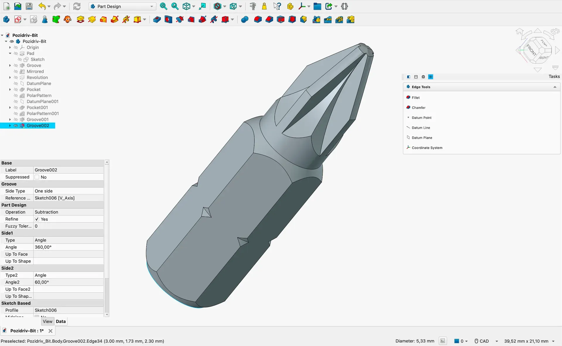
Part Design workbench: a screwdriver bit built from pad, groove, pocket and polar pattern features, with the Groove properties open.
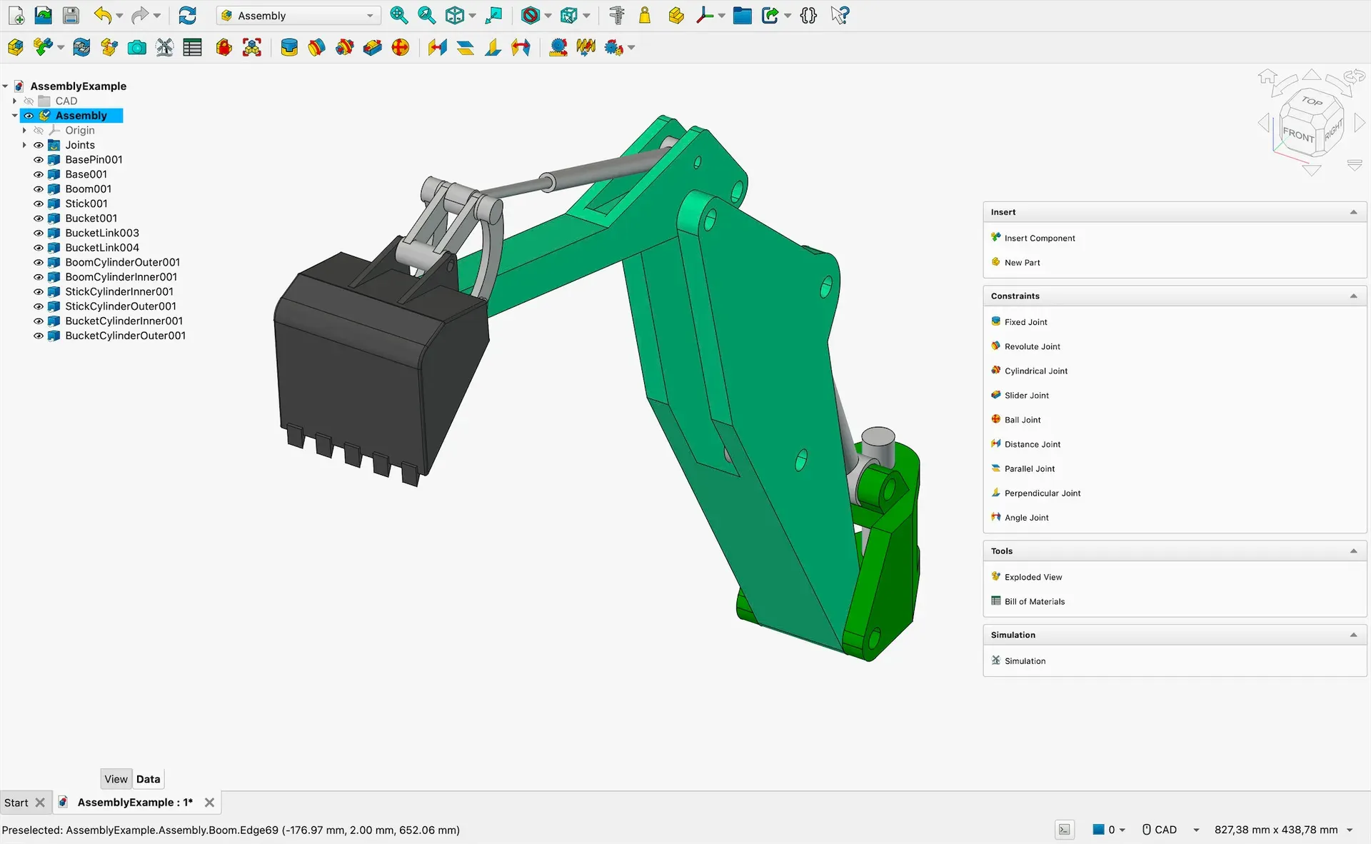
Assembly workbench: an excavator arm assembled with joints, with tools for exploded views, bill of materials and simulation.
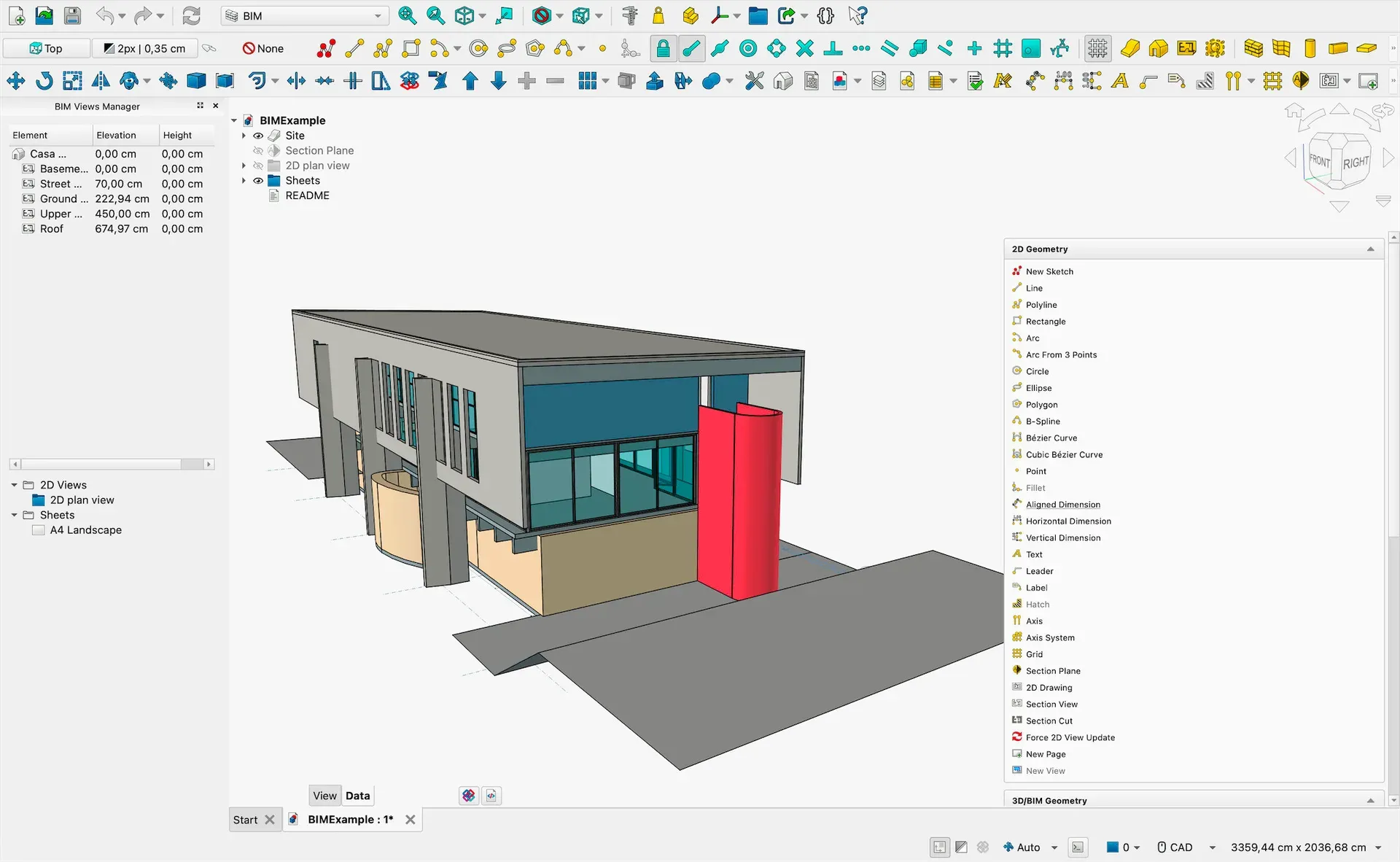
BIM workbench: a building model with levels, 2D views and sheets managed in the BIM Views panel.
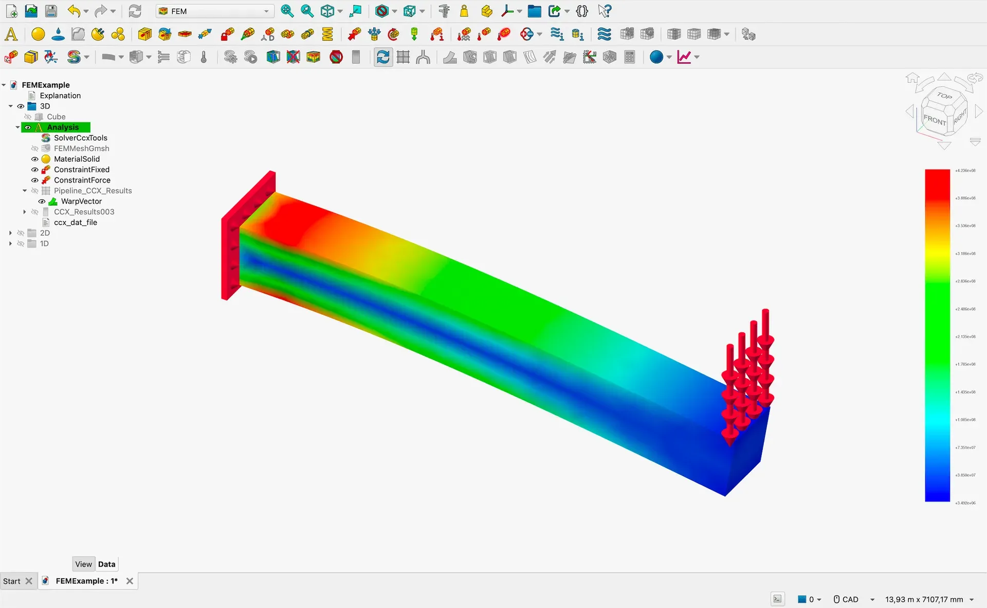
FEM workbench: a cantilever beam analysis solved with CalculiX, with results displayed on the deformed model.
Source: official FreeCAD project page.
Key capabilities
- Parametric modeling history All FreeCAD objects are natively parametric: shapes are based on properties that can be numbers, text, on/off switches or links to other objects. Shape changes are recalculated on demand and recorded in an undo/redo stack, so a design can be modified by going back into its history and changing parameters. Properties of one object can drive the properties of others, which allows custom parametric chains.
- Constraint-based 2D Sketcher The Sketcher workbench draws 2D geometry with an integrated constraint solver, so shapes are fixed by dimensional and geometric constraints. Sketches are the main building block in FreeCAD and serve as the base for features in Part Design and other workbenches. Version 1.1 added projection and intersection tools for external geometry.
- Part Design and Part workbenches Part Design builds solid bodies from sketches with features such as pad, pocket, revolution, groove, patterns, fillets, chamfers and holes, including threaded holes. The Part workbench works with primitives and Boolean operations directly on Open CASCADE shapes. Version 1.1 added transparent previews and interactive draggers for edge tools.
- Built-in Assembly workbench Since version 1.0, FreeCAD includes an Assembly workbench based on the Ondsel Solver. It defines joints such as fixed, revolute, cylindrical, slider, ball, distance, parallel, perpendicular and angle between parts, and offers exploded views, a bill of materials and a simulation tool for animating joint motion. Community assembly add-ons with other solvers remain available through the Addon Manager.
- BIM workbench for architecture In version 1.0 the former Arch workbench and the external BIM add-on were merged into a built-in BIM workbench for building and construction projects. It models walls, structures, windows, sites and levels, manages 2D views and sheets, and reads and writes IFC files, including native IFC handling. A BIM Views panel lists building levels with elevations.
- TechDraw production drawings TechDraw creates 2D technical drawings from 3D models on page templates, with projection groups, section and detail views, dimensions, hatching, annotations and symbols such as surface finish marks. Drawings stay linked to the model and update when it changes. Pages can be printed or exported, for example to PDF, SVG or DXF.
- Finite element analysis The FEM workbench prepares and runs structural, thermal and other analyses: it defines materials, constraints and loads, generates meshes with Gmsh or Netgen, and calls external solvers such as CalculiX and Elmer. Results are displayed in the 3D view with color scales, warp filters and post-processing pipelines. The solvers and meshers are separate programs that the workbench drives.
- CAM and CNC machining The CAM workbench creates jobs with stock, tools and operations such as contours and pockets, and translates the toolpaths into the G-code dialect of a target CNC controller through post processors. Version 1.1 introduced a new tool library system. The project home page also lists experimental CFD among the available engineering tools.
- Draft and 2D CAD The Draft workbench provides 2D drafting tools such as lines, polylines, arcs, B-splines, dimensions, text, arrays and snapping, and is also used to import and export DXF and DWG data. It is the base for many BIM tools. ShapeString turns text into geometry for engraving or extrusion.
- Mesh, Points, Surface and Reverse Engineering Separate workbenches handle polygon meshes (for example STL and OBJ for 3D printing), point clouds, NURBS surface creation and reverse engineering from scanned data. Mesh objects can be analysed, repaired and converted to solids. These tools sit beside the solid modeling workbenches rather than replacing them.
- Robot, Spreadsheet, OpenSCAD and Material Further built-in workbenches simulate industrial robot trajectories, store parameters in spreadsheets that can drive model dimensions, import OpenSCAD CSG files and manage material cards with physical and appearance properties. Spreadsheet values are often used to build families of parts from one model.
- File import and export FreeCAD reads and writes its native FCStd format and dozens of exchange formats, including STEP, IGES, STL, OBJ, DWG, DXF, SVG, SHP, DAE, IFC, OFF, NASTRAN, VRML and OpenSCAD CSG. Analysis results and quantities can also be exported. Add-on workbenches can add further formats.
- Python console, macros and scripting API Large parts of FreeCAD are written in Python, and almost everything in the application can be driven from Python: single commands in the integrated console, recorded macros, custom tools and complete workbenches. The power users hub documents the scripting API. Macro recording is also the method the README asks for when reproducing a bug.
- Addon Manager Community-made workbenches and macros can be installed, updated and removed from inside FreeCAD with the built-in Addon Manager. Add-ons are maintained by their own authors rather than by the core project.
- Real-world units and precision FreeCAD works in real-world units, from microns to kilometers, in metric or imperial systems or a mix of both. Models are full-precision solids suitable for export to 3D printing or CNC machining, and the measurement and quantity tools report values in the chosen unit schema.
- Download for Windows Windows 10 or later on x86_64: an installer (.exe) and a portable 7z archive, both with SHA256 checksum files. The project states that Windows builds are signed by The FreeCAD project association AISBL. Weekly development builds are also available as separate pre-releases.
- Download for macOS MacOS 12 Monterey or later: separate DMG images for Apple Silicon (arm64) and Intel (x86_64), each with a SHA256 file and signed by the FPA. Installation details are described on the wiki download and installation pages.
- Download for Linux AppImages for x86_64 and aarch64 with SHA256 and zsync files are published on the release page. The README notes that FreeCAD can also be installed from the software center of most Linux distributions, and the download page mentions Snap and Flatpak channels for development builds.
- Community and documentation Documentation lives on the FreeCAD wiki, with getting-started guides, a feature list, workbench pages and tutorials, and developer material is in the Developers Handbook. Help is available on the official forum, Discord and the r/FreeCAD subreddit, and bugs are tracked in GitHub issues. The interface is translated through Crowdin.
Where FreeCAD fits
Mechanical part design from sketches
A typical mechanical workflow starts in the Sketcher with a fully constrained profile, which is then turned into a solid in Part Design with pads, pockets, revolutions, holes and patterns. Dimensions can be named or linked to a spreadsheet so a whole part updates when a parameter changes. The model tree keeps every feature, and a feature can be edited later without rebuilding the part by hand.
Assemblies and motion studies
Parts are inserted into an assembly and connected with joints such as revolute, slider or distance joints in the built-in Assembly workbench. The workbench can produce exploded views and a bill of materials, and its simulation tool animates joint motion, as shown in the excavator example in the FreeCAD README. Parts from external files can be linked rather than copied.
Technical drawings for manufacturing
TechDraw places projection groups, sections and detail views of a 3D model on a page template and adds dimensions, tolerances, hatching and annotations. Because views are linked to the model, a change in Part Design updates the drawing. Pages are exported to PDF, SVG or DXF for production or review.
Building and architecture models with IFC
The BIM workbench models sites, levels, walls, structures and windows, generates 2D plans and sections, and exchanges data with other BIM applications through IFC. The project describes it as making building and construction projects possible without extra add-ons since version 1.0, and later releases added native IFC support for 2D objects.
Structural analysis with FEM
An FEM analysis container holds the material, fixed and force constraints, a mesh from Gmsh or Netgen and a solver object such as CalculiX. After the solver runs, results such as stress or displacement are shown on the model with a color scale and can be filtered in post-processing pipelines. The analysis stays tied to the parametric geometry, so a design change can be re-meshed and re-solved.
3D printing, CNC and scripted automation
Finished solids are exported as STL, OBJ or 3MF for slicers, or turned into toolpaths and G-code in the CAM workbench. Repetitive work can be recorded as a macro or written in Python against the FreeCAD API, from a single console command to a complete custom workbench. Similar open-source projects in the directory include SolidCraft for parametric 3D CAD and CADCraft for 2D CAD.
Reviews of FreeCAD
Be the first to share your experience with FreeCAD.
Write a review
Loading review form…
Alternatives to FreeCAD
 SolidCraftSolidCraft is parametric 3D CAD written in Rust and licensed MIT OR Apache-2.0. Sketch with constraints, build solids on an editable timeline and rebuild by changing parameters, on Windows, macOS, Linux, FreeBSD or in the browser, with a CLI and an MCP server.
 CADCraftCADCraft is a pre-alpha, clean-room 2D drafting application written in Rust by the ArtCraft team. It opens and saves DXF and DWG, plots layouts to PDF, runs AutoLISP and scripts, and offers a headless CLI and MCP server on Windows, macOS, Linux, FreeBSD and the web.